
Use case diagram (PlantUML)
Use case diagrams are for scope conversations with people who will not read a technical diagram. The boundary is the whole point.
#What this example shows
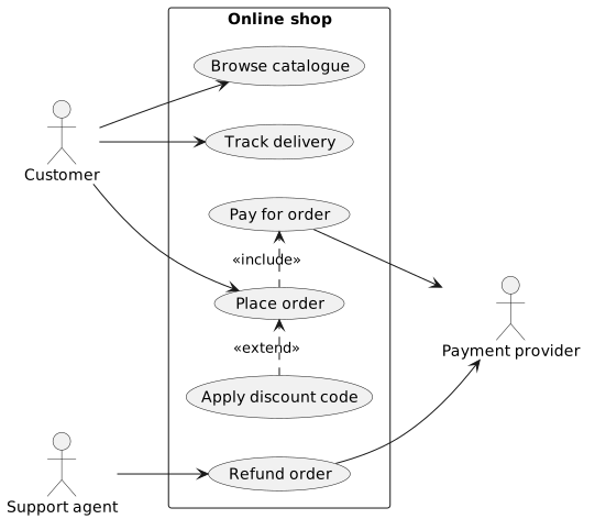
A rectangle acting as the system boundary.
include and extend, which mean different things.
An external system drawn as an actor on the right.
#A worked example
Open it, edit it, or copy the source below.
The source, which you can paste into a new diagram and edit:
#Making it your own
include means always; extend means sometimes. Swapping them changes the meaning.
left to right direction usually reads better for use case diagrams.
Keep use cases at the level of goals, not steps.
#Related
Verbose, stable, and it draws almost everything.