
Memory layout diagram
A memory or binary layout diagram is a grid of fields with byte offsets, and Bytefield exists to draw exactly that. It handles nested structures and variable-length regions, which is where hand-drawn versions fall apart.
It is the diagram that turns a struct definition into something a person can hold in their head.
#When to reach for one
File format and binary protocol documentation.
Embedded work: register maps, EEPROM layouts, flash partitions.
Explaining alignment and padding, which nobody believes until they see it.
#How to draw it in Capable
Route | Use when |
|---|---|
Bytefield | Byte-oriented layouts with offsets, nesting and gaps. |
PacketDiag | Bit-oriented network headers with a fixed word width. |
#A worked example
A record header with a fixed part and a variable payload:
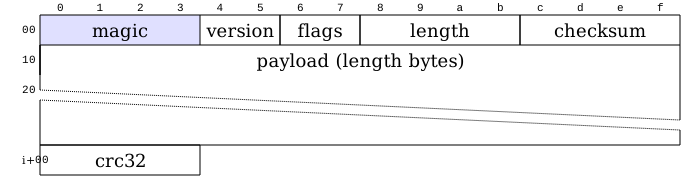
The source, which you can paste into a new diagram and edit:
#A few things that catch people out
State the endianness once, at the top. Half of all binary format bugs start here.
Draw padding explicitly. Invisible padding is what breaks a struct on a different compiler.
Use a gap for variable-length regions rather than pretending they have a fixed size.
#Related
Approximately right is wrong here.