
Component diagram
Component diagrams show structure at the level of deployable or replaceable parts, with explicit provided and required interfaces. That interface detail is what separates them from a block diagram.
Useful when the contract between parts is the subject.
#When to draw one
Documenting a plugin or module architecture.
Explaining what a component needs in order to run.
Design reviews where interface boundaries are the debate.
#What is on the diagram
Element | Meaning |
|---|---|
Component | A replaceable part with defined interfaces |
Provided interface | A lollipop: what it offers |
Required interface | A socket: what it needs |
Port | A named connection point on a component |
Assembly connector | A provided interface plugged into a required one |
#A worked example
Components with provided and required interfaces:
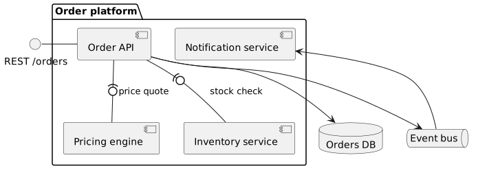
The source, which you can paste into a new diagram and edit:
#A few things that catch people out
Draw the interfaces, not just the boxes. Without them it is a block diagram.
A component that requires six interfaces is doing too much, and the diagram says so.
Keep deployment out of it; that is a deployment diagram's job.
#Related
Four types cover most of it.