
Packet and protocol headers
A header diagram is a grid of fields with bit widths, and drawing it by hand is miserable. PacketDiag and Bytefield both generate one from a short text description, and they get the offsets right.
This is the diagram that makes a binary protocol specification readable.
#When to reach for one
Documenting a custom binary protocol or file format.
Explaining an existing protocol header in a design document.
Debugging, where the field boundaries are the question.
#How to draw it in Capable
Route | Use when |
|---|---|
PacketDiag | Network-style headers with bit offsets across a fixed width. |
Bytefield | Byte-oriented structures, including nested and variable sections. |
#A worked example
A TCP header, generated from field widths:
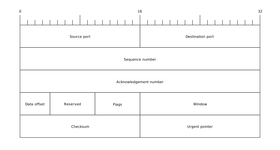
The source, which you can paste into a new diagram and edit:
#A few things that catch people out
Set the column width to the real word size or the offsets will mislead.
Say whether you are counting bits or bytes, once, at the top.
Variable-length fields need a note; the grid cannot express them on its own.
#Related
Somebody will read this at 3am. Be kind.