
Network diagram
Network diagrams are drawn for two audiences: people fixing something now, and people planning something later. The first needs addresses and device names, the second needs shapes and boundaries.
Decide which one you are drawing before you start, and say so on the page.
#When to reach for one
Documenting an office or site network so it can be supported.
Planning a change, where the current state has to be agreed first.
Security reviews, where the boundaries are the point.
#How to draw it in Capable
Route | Use when |
|---|---|
draw.io | The usual answer: real network shapes and precise layout. |
nwdiag | Generated layout from text, with networks as labelled bands. |
#A worked example
Three networks with their addresses, generated from text:
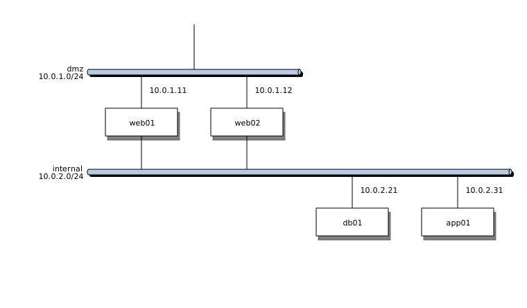
The source, which you can paste into a new diagram and edit:
#A few things that catch people out
Put addresses on the diagram if it is for support, and leave them off if it is for a slide.
A device on two networks should appear once, on both bands. nwdiag does this for you.
Date it. Network diagrams are the fastest-ageing documents in most organisations.
#Related
Somebody will read this at 3am. Be kind.