
Circuit diagram (TikZ)
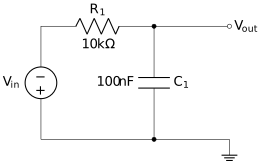
Circuit symbols are standardised, and circuitikz draws them correctly. This is a simple RC low-pass filter with a labelled supply.
#What this example shows
circuitikz, which supplies the electrical symbol set.
Component values on every part.
A correct ground symbol.
#A worked example
Open it, edit it, or copy the source below.
The source, which you can paste into a new diagram and edit:
#Making it your own
TikZ is disabled by default; an administrator turns it on.
The american or european option changes the resistor symbol. Pick one and stay with it.
Label component values, or the schematic documents topology only.
#Related
Exact, or not worth drawing.