Add diagrams to Markdown
Visualize processes, architecture and organizations easily inside your Markdown content.
Incorporating diagrams into your Markdown documents can greatly enhance understanding and visualization of complex information.
This guide covers how to use various diagramming tools supported by our platform directly within your Markdown files.
Just want to insert a diagram?
Use the diagrams feature to insert individual diagrams with enhanced functionality.
Basic Syntax and Steps
To insert a diagram, you encapsulate the diagram code within code blocks. Each tool may use slightly different syntax or keywords, so it's important to refer to the specific documentation for each diagramming tool. However, the basic pattern is as follows:
```language
<diagram code here>
```
Where:
language is the name of the diagram framework (e.g. mermaid)
diagram code is framework-specific syntax for that library
Supported Diagram Types
Our platform supports a wide range of diagramming tools, allowing you to create everything from simple flowcharts to complex network diagrams. Here are the diagram types you can include:
Flowcharts, Sequence Diagrams, and Activity Diagrams: Tools like Mermaid, PlantUML, and ActDiag.
Network and Rack Diagrams: Tools such as NwDiag and RackDiag.
Database and ER Diagrams: Tools like DBML, Erd, and PlantUML.
Architectural Diagrams: Tools like C4 with PlantUML and Structurizr.
Graphical Diagrams: Tools such as GraphViz and Vega.
Custom and Creative Diagrams: Tools like Excalidraw and Pikchr.
Examples
Mermaid Diagrams
Mermaid simplifies the creation of diagrams and flowcharts with its Markdown-like script, enabling easy generation of sequence, Gantt, class, and flowcharts, directly in web-based tools.
```mermaid
graph LR
  A[Start] --> B{Decision}
  B -- Yes --> C[Do Thing]
  B -- No --> D[Do Other Thing]
  C --> D
  D --> E[End]
```
PlantUML Diagrams
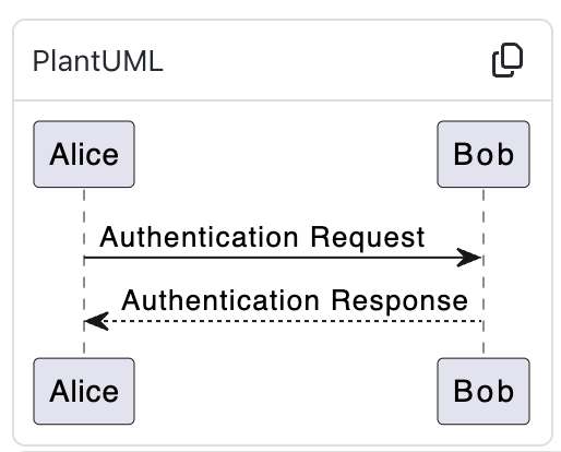
PlantUML is versatile in generating UML diagrams (and other types) from a simple text description, widely used in software development for documenting architecture and processes.
```plantuml
@startuml
Alice -> Bob: Authentication Request
Bob --> Alice: Authentication Response
@enduml
```
DBML Diagrams
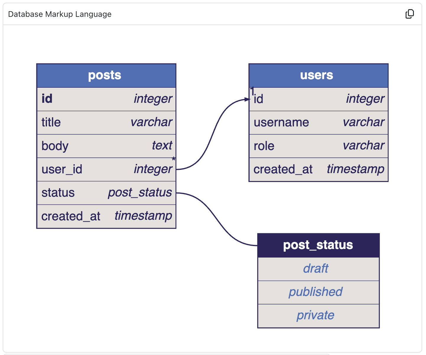
DBML (Database Markup Language) is focused on defining and visualizing database schemas, providing a clear and readable syntax for database design.
```dbml
Table users {
  id integer
  username varchar
  role varchar
  created_at timestamp
}

Table posts {
  id integer [primary key]
  title varchar
  body text [note: 'Content of the post']
  user_id integer
  status post_status
  created_at timestamp
}

Enum post_status {
  draft
  published
  private [note: 'visible via URL only']
}

Ref: posts.user_id > users.id // many-to-one
```
BPMN Diagrams
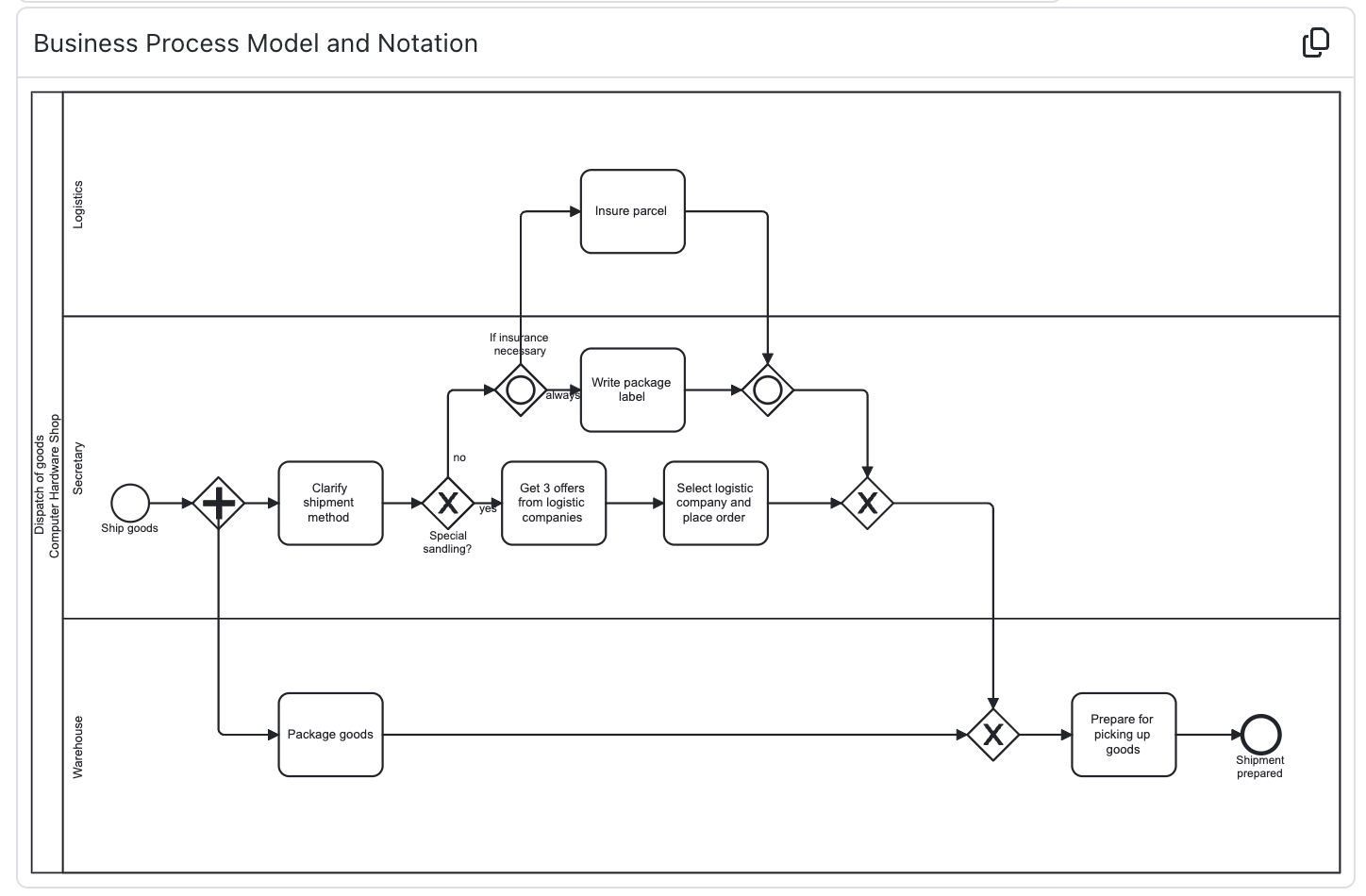
BPMN (Business Process Model and Notation) provides a standard way to visualize business processes, allowing for detailed modeling of sequences, decisions, and business interactions.
```bpmn
<?xml version="1.0" encoding="UTF-8"?>
<bpmn:definitions xmlns:xsi="http://www.w3.org/2001/XMLSchema-instance" xmlns:bpmn="http://www.omg.org/spec/BPMN/20100524/MODEL" xmlns:bpmndi="http://www.omg.org/spec/BPMN/20100524/DI" xmlns:dc="http://www.omg.org/spec/DD/20100524/DC" xmlns:di="http://www.omg.org/spec/DD/20100524/DI" id="Definitions_1ntn90c" targetNamespace="http://bpmn.io/schema/bpmn" exporter="bpmn-js (https://demo.bpmn.io)" exporterVersion="17.3.0">
  <bpmn:process id="Process_0fzjgu7" isExecutable="false">
    <bpmn:startEvent id="StartEvent_13ja4v3">
      <bpmn:outgoing>Flow_1m0cjk1</bpmn:outgoing>
    </bpmn:startEvent>
    <bpmn:task id="Activity_0jswg8s" name="Step">
      <bpmn:incoming>Flow_1m0cjk1</bpmn:incoming>
    </bpmn:task>
    <bpmn:sequenceFlow id="Flow_1m0cjk1" sourceRef="StartEvent_13ja4v3" targetRef="Activity_0jswg8s" />
  </bpmn:process>
  <bpmndi:BPMNDiagram id="BPMNDiagram_1">
    <bpmndi:BPMNPlane id="BPMNPlane_1" bpmnElement="Process_0fzjgu7">
      <bpmndi:BPMNShape id="_BPMNShape_StartEvent_2" bpmnElement="StartEvent_13ja4v3">
        <dc:Bounds x="156" y="82" width="36" height="36" />
      </bpmndi:BPMNShape>
      <bpmndi:BPMNShape id="Activity_0jswg8s_di" bpmnElement="Activity_0jswg8s">
        <dc:Bounds x="310" y="60" width="100" height="80" />
        <bpmndi:BPMNLabel />
      </bpmndi:BPMNShape>
      <bpmndi:BPMNEdge id="Flow_1m0cjk1_di" bpmnElement="Flow_1m0cjk1">
        <di:waypoint x="192" y="100" />
        <di:waypoint x="310" y="100" />
      </bpmndi:BPMNEdge>
    </bpmndi:BPMNPlane>
  </bpmndi:BPMNDiagram>
</bpmn:definitions>
```
C4 Diagrams
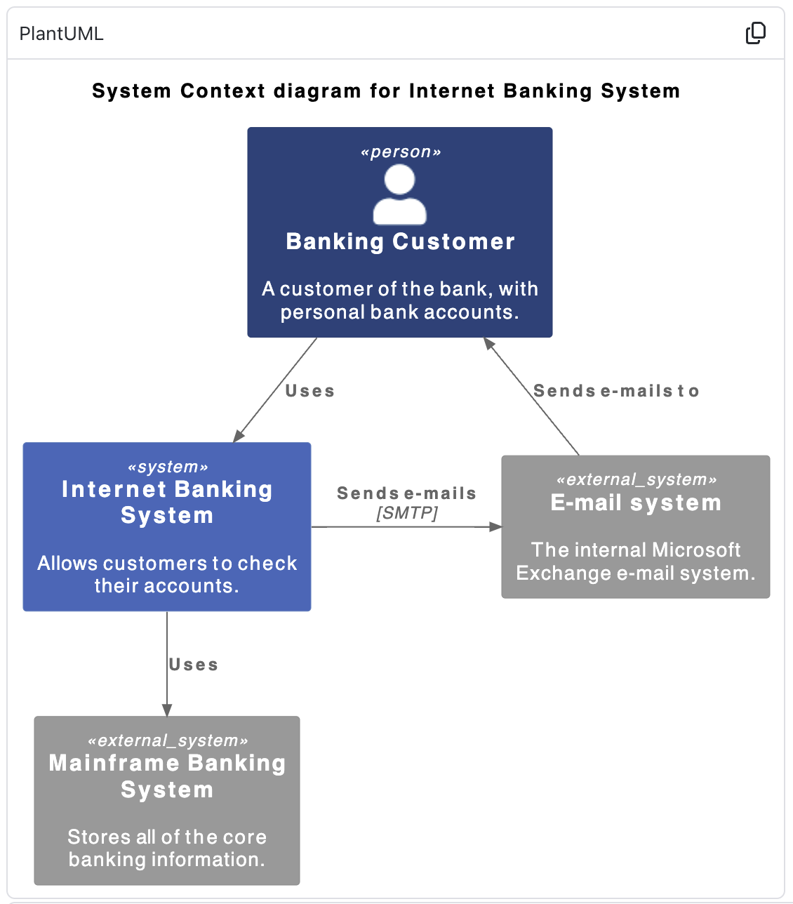
C4 with PlantUML integrates the C4 model for visualizing software architectures with PlantUML, enabling clear and structured diagrams of software systems.
```plantuml
!include <C4/C4_Context>

title System Context diagram for Internet Banking System

Person(customer, "Banking Customer", "A customer of the bank, with personal bank accounts.")
System(banking_system, "Internet Banking System", "Allows customers to check their accounts.")

System_Ext(mail_system, "E-mail system", "The internal Microsoft Exchange e-mail system.")
System_Ext(mainframe, "Mainframe Banking System", "Stores all of the core banking information.")

Rel(customer, banking_system, "Uses")
Rel_Back(customer, mail_system, "Sends e-mails to")
Rel_Neighbor(banking_system, mail_system, "Sends e-mails", "SMTP")
Rel(banking_system, mainframe, "Uses")
```
.png)